Frame Design

Project Description
In this project, we were given the opportunity to design an engine mount on Inventor and test the design's efficiency with the frame analysis function. However, in this project there were a variety of constraints. First, our design had to meet the requirement that the firewall of the design must be grounded as a stable part of the design. In addition, we had to use constraints on each of the pipes attached to the firewall. Next, the structure must support the Lycoming O-300 engine which is 250 lbs and must be attached to the three plates.
Procedure
In class, we did a variety of activities to prepare ourselves for this project. These activities most importantly allowed us to become successful in this project. First, we evaluated different materials that are used in aerospace to determine their characteristics and their potential uses in aerospace design. This activity tremendously helped us understand the importance of the materials in aerospace design and the cost efficiency of the design. After this activity in class, we directed our attention to the tutorials on Inventor. These activities allowed us to understand the uses of Inventor on aerospace design and the purpose of using Inventor for aerospace design. The first tutorial on Inventor that we completed taught us how to make a frame. This is very important because all aircraft designs consist of a frame inside of the fuselage. The next tutorial on Inventor that we completed taught us how to execute a frame analysis on a specific aerospace design. This was important because it allows us to evaluate how efficient our design is and the potential weaknesses of our design.
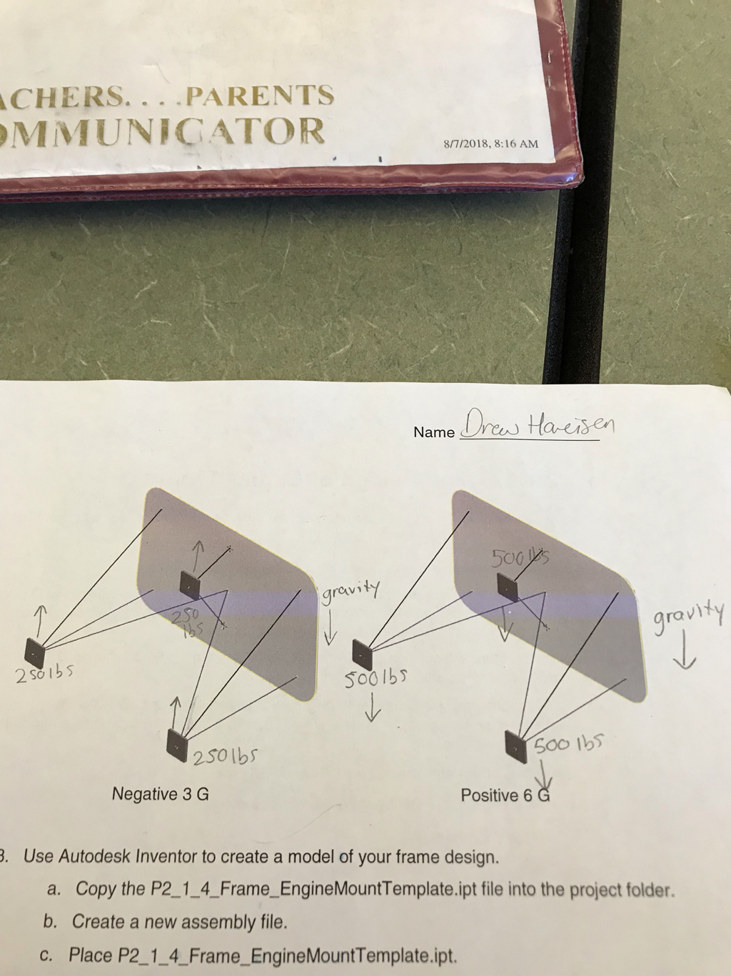
In this project, we had to design an engine mount for a Lycoming O-300. We designed the engine mount by taking an engine mount template and then applying our knowledge to make the design more efficient. First, we had to insert a frame along the pipe areas of the design in order to construct the engine mount. Next, we had to trim and extend each pipe to the fire wall and plates to create a flawless design. In addition, we had to miter the joints of the pipes. This is an important step to increase the strength of the pips and allows the pipes to join together properly. After completing these steps we were able to create the engine mount properly and correctly. Furthermore, the engine mount must tested at negative 3 gs and 6 gs of force to account for the maneuvers of a Lycoming O-300. Also, the pipes must be ANSI 1.5 in. and frames must be properly mitered. By accomplishing these tasks we will be able to successfully complete this project.
The different skills we used were mitering joints, trimming pipes, and extending pipes. This skills we developed throughout the previous activities we completed in class and throughout the tutorials on Inventor. These skills are important and crucial to making our design applicable to a real life situation. Overall, by using these skills our design becomes stronger and more efficient.
Solution
In the testing of negative 3 gs of force it was relatively apparent that the longest pipes that hold the engine experienced the most force. In contrast the shortest beam experienced the least amount of force during the negative 3 gs test. The explanation for this is quite simple because the longer pipes would have the greatest moment when 250 lbs of force acted on them. In the testing of 6 gs the results were almost exactly the same because the longest pipes experienced the most force while the shortest beams experienced the least amount of force.
Our design meets the constraint because of a variety of reasons. First, the firewall is grounded as the stable point of the design. Next, the design will support a Lycoming O-300 engine which is 250 lbs. In addition, our design was tested at negative 3 gs and 6 gs and successfully supported these weights. Finally, our design was constructed of ANSI 1.5 in pipes and were mitered at all the proper points.
Our design used mild steel. We used this because this material has a high strength and is heat resistant. This is important because the engine is very heavy and can become very hot. Also, mild steel is cheaper than the other forms of steel which makes our design more cost efficient for its design. This will make it more affordable for the consumer of our design.

The picture above shows the engine mount when it is exposed to negative 3 gs of force.
|

The picture above shows the engine mount when it is exposed to 6 gs of force.
|
Conclusion
In this project, I learned how to use Inventor for aerospace designs and how to use frame analysis in order to test the strength of our design. In addition, I learned the properties of many materials that are used in aerospace and there uses in the aerospace industry. This project, also, taught me how to effectively work as a team and complete a task. Overall, all the skills and knowledge I learned throughout this project will greatly help me in aerospace class and more importantly will help me become a better student.
During this project, I worked on Inventor while my partner did the calculations and gathered the pictures for the Weebly. Overall, my partner and me did a great job of working together and doing equal amounts of work.
I strongly believe that the frame generator is a useful tool for aerospace engineers because of a few reasons. First, it allows the user to construct a frame for the aircraft. This is very important in designing an air craft because the frame supports the entire aircraft. Next, the frame generator allows the user to test their designs to evaluate the strength and efficiency of their design. Overall, the frame generator can be used throughout all the steps of designing a prototype in aerospace engineering.
